MOTOR Genphoal Technology, Inc. 2017-07-23T11:47:46Z https://www.andmotor.com/feed/atom/ WordPress admin <![CDATA[Brushless DC electric motor]]> http://rttheme19.rtthemes.com/2015/02/19/gallery-post-type-3/ 2017-05-25T07:53:51Z 2015-02-19T23:03:20Z Brushless DC electric motor BLDC motors, BL motors also known as electronically commutated motors (ECMs, EC motors) are synchronous motors powered by DC electricity via an inverter/switching power supply which produces an AC/bi-directional electric current to drive each phase of the motor via a closed loop controller. The controller times commutation (hence rpm) and creates […]

The post Brushless DC electric motor appeared first on MOTOR.

]]>
Brushless DC electric motor

BLDC motors, BL motors also known as electronically commutated motors (ECMs, EC motors) are synchronous motors powered by DC electricity via an inverter/switching power supply which produces an AC/bi-directional electric current to drive each phase of the motor via a closed loop controller. The controller times commutation (hence rpm) and creates current waveforms (hence torque). In this context alternating current does not imply but does include a sinusoidal waveform, with minimal restriction on waveform; it must be periodic, and its frequency will determine motor rpm, and the waveform does affect how smooth the generated torque is as well as the motors efficiency at transforming electrical to mechanical energy. In a well designed PMSM the air gap magnetic flux is spatial sinusoidal and the phase commutation currents are sinusoidal, ninety degrees out of phase.
The motor structural elements of a brushless motor system is typically permanent magnet synchronous motor, but can also be a switched reluctance motor, or induction motor.

Brushless motors may be implemented as stepper motors as well; however, the term “stepper motor” tends to be used for motors with a radically different design and controlled with an open loop (hence the controller cannot detect when the stepper does not step due to too high shaft load; there is no shaft position sensor). They are frequently stopped with the rotor in a defined angular position while still producing torque. A well design power supply/controller/PMSM can also be held at zero rpm and finite torque. Two key performance parameters of brushless DC motors are the motor constants Kt ( torque constant) and Ke ( BEMF constant also known as speed constant Kv = 1/Ke ).

Brushless vs brushed motors (Brushless DC electric motor)

Brushed DC motors have been around since the mid-19th century, but brushless motors are a fairly recent arrival; a first step in the 1960s thanks to advances in solid state technology,[3] with further improvements in the 1980s thanks to better permanent magnet materials.

Brushed DC motors develop a maximum torque when stationary, linearly decreasing as velocity increases.[4] Some limitations of brushed motors can be overcome by brushless motors; they include higher efficiency and a lower susceptibility to mechanical wear. These benefits come at the cost of potentially less rugged, more complex, and more expensive control electronics.

A typical brushless motor has permanent magnets which rotate around a fixed armature, eliminating problems associated with connecting current to the moving armature. An electronic controller replaces the brush/commutator assembly of the brushed DC motor, which continually switches the phase to the windings to keep the motor turning. The controller performs similar timed power distribution by using a solid-state circuit rather than the brush/commutator system.

Brushless motors offer several advantages over brushed DC motors, including high torque to weight ratio, more torque per watt (increased efficiency), increased reliability, reduced noise, longer lifetime (no brush and commutator erosion), elimination of ionizing sparks from the commutator, and overall reduction of electromagnetic interference (EMI). With no windings on the rotor, they are not subjected to centrifugal forces, and because the windings are supported by the housing, they can be cooled by conduction, requiring no airflow inside the motor for cooling. This in turn means that the motor’s internals can be entirely enclosed and protected from dirt or other foreign matter.

Brushless motor commutation can be implemented in software using a microcontroller or microprocessor computer, or may alternatively be implemented in analogue hardware, or in digital firmware using an FPGA. Commutation with electronics instead of brushes allows for greater flexibility and capabilities not available with brushed DC motors, including speed limiting, “micro stepped” operation for slow and/or fine motion control, and a holding torque when stationary. Controller software can be customized to the specific motor being used in the application, resulting in greater commutation efficiency.

The maximum power that can be applied to a brushless motor is limited almost exclusively by heat;[citation needed] too much heat weakens the magnets[5] and may damage the winding’s insulation.

When converting electricity into mechanical power, brushless motors are more efficient than brushed motors. This improvement is largely due to the frequency at which the electricity is switched determined by the position sensor feedback. Additional gains are due to the absence of brushes, which reduces mechanical energy loss due to friction. The enhanced efficiency is greatest in the no-load and low-load region of the motor’s performance curve.[citation needed] Under high mechanical loads, brushless motors and high-quality brushed motors are comparable in efficiency.

The post Brushless DC electric motor appeared first on MOTOR.

]]>
0
admin <![CDATA[synchronous motor]]> http://rttheme19.rtthemes.com/2015/02/19/self-hosted-video-post-2-2/ 2017-05-25T08:41:09Z 2015-02-19T23:03:20Z synchronous motor is an AC motor in which, at steady state, the rotation of the shaft is synchronized with the frequency of the supply current; the rotation period is exactly equal to an integral number of AC cycles. Synchronous motors contain multiphase AC electromagnets on the stator of the motor that create a magnetic field […]

The post synchronous motor appeared first on MOTOR.

]]>
synchronous motor

is an AC motor in which, at steady state, the rotation of the shaft is synchronized with the frequency of the supply current; the rotation period is exactly equal to an integral number of AC cycles. Synchronous motors contain multiphase AC electromagnets on the stator of the motor that create a magnetic field which rotates in time with the oscillations of the line current. The rotor with permanent magnets or electromagnets turns in step with the stator field at the same rate and as a result, provides the second synchronized rotating magnet field of any AC motor. A synchronous motor is only considered doubly fed if it is supplied with independently excited multiphase AC electromagnets on both the rotor and stator.The synchronous motor and induction motor are the most widely used types of AC motor. The difference between the two types is that the synchronous motor rotates in exact synchronism with the line frequency. The synchronous motor does not rely on current induction to produce the rotor’s magnetic field. By contrast, the induction motor requires “slip”, the rotor must rotate slightly slower than the AC current alternations, to induce current in the rotor winding. Small synchronous motors are used in timing applications such as in synchronous clocks, timers in appliances, tape recorders and precision servomechanisms in which the motor must operate at a precise speed; speed accuracy is that of the power line frequency, which is carefully controlled in large interconnected grid systems.

Synchronous motors are available in sub-fractional self-excited sizes to high-horsepower industrial sizes. In the fractional horsepower range, most synchronous motors are used where precise constant speed is required. These machines are commonly used in analog electric clocks, timers and other devices where correct time is required. In high-horsepower industrial sizes, the synchronous motor provides two important functions. First, it is a highly efficient means of converting AC energy to work. Second, it can operate at leading or unity power factor and thereby provide power-factor correction.

Type

Synchronous motors fall under the more general category of synchronous machines which also includes the synchronous generator. Generator action will be observed if the field poles are “driven ahead of the resultant air-gap flux by the forward motion of the prime mover”. Motor action will be observed if the field poles are “dragged behind the resultant air-gap flux by the retarding torque of a shaft load”.

There are two major types of synchronous motors depending on how the rotor is magnetized: non-excited and direct-current excited.
Non-excited motors  Single-phase 60 Hz 1800 RPM synchronous motor for Teletype machine, non-excited rotor type, manufactured from 1930 to 1955.

In non-excited motors, the rotor is made of steel. At synchronous speed it rotates in step with the rotating magnetic field of the stator, so it has an almost-constant magnetic field through it. The external stator field magnetizes the rotor, inducing the magnetic poles needed to turn it. The rotor is made of a high-retentivity steel such as cobalt steel, These are manufactured in permanent magnet, reluctance and hysteresis designs:

Reluctance motors

These have a rotor consisting of a solid steel casting with projecting (salient) toothed poles. Typically there are fewer rotor than stator poles to minimize torque ripple and to prevent the poles from all aligning simultaneously—a position which cannot generate torque. The size of the air gap in the magnetic circuit and thus the reluctance is minimum when the poles are aligned with the (rotating) magnetic field of the stator, and increases with the angle between them. This creates a torque pulling the rotor into alignment with the nearest pole of the stator field. Thus at synchronous speed the rotor is “locked” to the rotating stator field. This cannot start the motor, so the rotor poles usually have squirrel-cage windings embedded in them, to provide torque below synchronous speed. The machine starts as an induction motor until it approaches synchronous speed, when the rotor “pulls in” and locks to the rotating stator field.

Reluctance motor designs have ratings that range from fractional horsepower (a few watts) to about 22 kW. Very small reluctance motors have low torque, and are generally used for instrumentation applications. Moderate torque, integral horsepower motors use squirrel cage construction with toothed rotors. When used with an adjustable frequency power supply, all motors in the drive system can be controlled at exactly the same speed. The power supply frequency determines motor operating speed.

Hysteresis motors

These have a solid smooth cylindrical rotor, cast of a high coercivity magnetically “hard” cobalt steel.This material has a wide hysteresis loop (high coercivity), meaning once it is magnetized in a given direction

The post synchronous motor appeared first on MOTOR.

]]>
0
admin <![CDATA[Induction motor]]> http://rttheme19.rtthemes.com/2015/02/19/self-hosted-video-post-2/ 2017-05-25T08:16:50Z 2015-02-19T23:03:20Z Induction motor Three-phase totally enclosed fan-cooled (TEFC) induction motor with end cover on the left, and without end cover to show cooling fan. In TEFC motors, interior heat losses are dissipated indirectly through enclosure fins, mostly by forced air convection.Cutaway view through stator of TEFC induction motor, showing rotor with internal air circulation vanes. Many […]

The post Induction motor appeared first on MOTOR.

]]>
Induction motor

Three-phase totally enclosed fan-cooled (TEFC) induction motor with end cover on the left, and without end cover to show cooling fan. In TEFC motors, interior heat losses are dissipated indirectly through enclosure fins, mostly by forced air convection.Cutaway view through stator of TEFC induction motor, showing rotor with internal air circulation vanes. Many such motors have a symmetric armature, and the frame may be reversed to place the electrical connection box (not shown) on the opposite side.

An induction motor or 3 phase induction motor is an AC electric motor in which the electric current in the rotor needed to produce torque is obtained by electromagnetic induction from the magnetic field of the stator winding.[1] An induction motor can therefore be made without electrical connections to the rotor.[a] An induction motor’s rotor can be either wound type or squirrel-cage type.

Three-phase squirrel-cage induction motors are widely used in industrial drives because they are rugged, reliable and economical. Single-phase induction motors are used extensively for smaller loads, such as household appliances like fans. Although traditionally used in fixed-speed service, induction motors are increasingly being used with variable-frequency drives (VFDs) in variable-speed service. VFDs offer especially important energy savings opportunities for existing and prospective induction motors in variable-torque centrifugal fan, pump and compressor load applications. Squirrel cage induction motors are very widely used in both fixed-speed and variable-frequency drive (VFD) applications.

History
A model of Tesla’s first induction motor, in Tesla Museum, Belgrade
Squirrel cage rotor construction, showing only the center three laminations

In 1824, the French physicist François Arago formulated the existence of rotating magnetic fields, termed Arago’s rotations. By manually turning switches on and off, Walter Baily demonstrated this in 1879, effectively the first primitive induction motor.

The first AC commutator-free induction motors were independently invented by Galileo Ferraris and Nikola Tesla, a working motor model having been demonstrated by the former in 1885 and by the latter in 1887. Tesla applied for US patents in October and November 1887 and was granted some of these patents in May 1888. In April 1888, the Royal Academy of Science of Turin published Ferraris’s research on his AC polyphase motor detailing the foundations of motor operation. In May 1888 Tesla presented the technical paper A New System for Alternating Current Motors and Transformers to the American Institute of Electrical Engineers (AIEE)describing three four-stator-pole motor types: one with a four-pole rotor forming a non-self-starting reluctance motor, another with a wound rotor forming a self-starting induction motor, and the third a true synchronous motor with separately excited DC supply to rotor winding.

George Westinghouse, who was developing an alternating current power system at that time, licensed Tesla’s patents in 1888 and purchased a US patent option on Ferraris’ induction motor concept.Tesla was also employed for one year as a consultant. Westinghouse employee C. F. Scott was assigned to assist Tesla and later took over development of the induction motor at Westinghouse.Steadfast in his promotion of three-phase development, Mikhail Dolivo-Dobrovolsky invented the cage-rotor induction motor in 1889 and the three-limb transformer in 1890.Furthermore, he claimed that Tesla’s motor was not practical because of two-phase pulsations, which prompted him to persist in his three-phase work.Although Westinghouse achieved its first practical induction motor in 1892 and developed a line of polyphase 60 hertz induction motors in 1893, these early Westinghouse motors were two-phase motors with wound rotors until B. G. Lamme developed a rotating bar winding rotor.

The General Electric Company (GE) began developing three-phase induction motors in 1891. By 1896, General Electric and Westinghouse signed a cross-licensing agreement for the bar-winding-rotor design, later called the squirrel-cage rotor.Arthur E. Kennelly was the first to bring out the full significance of complex numbers (using j to represent the square root of minus one) to designate the 90º rotation operator in analysis of AC problems.GE’s Charles Proteus Steinmetz greatly developed application of AC complex quantities including an analysis model now commonly known as the induction motor Steinmetz equivalent circuit.

Induction motor improvements flowing from these inventions and innovations were such that a 100-horsepower induction motor currently has the same mounting dimensions as a 7.5-horsepower motor in 1897.

The post Induction motor appeared first on MOTOR.

]]>
0
admin <![CDATA[stepper motor]]> http://rttheme19.rtthemes.com/2015/02/19/gallery-post-type-2-2/ 2017-05-25T08:47:59Z 2015-02-19T23:03:20Z stepper motor step motor or stepping motor is a brushless DC electric motor that divides a full rotation into a number of equal steps. The motor’s position can then be commanded to move and hold at one of these steps without any feedback sensor (an open-loop controller), as long as the motor is carefully sized […]

The post stepper motor appeared first on MOTOR.

]]>
stepper motor

step motor or stepping motor is a brushless DC electric motor that divides a full rotation into a number of equal steps. The motor’s position can then be commanded to move and hold at one of these steps without any feedback sensor (an open-loop controller), as long as the motor is carefully sized to the application in respect to torque and speed. Switched reluctance motors are very large stepping motors with a reduced pole count, and generally are closed-loop commutated.

Fundamentals of operation
A stepper motor
A bipolar hybrid stepper motor

Brushed DC motors rotate continuously when DC voltage is applied to their terminals. The stepper motor is known by its property to convert a train of input pulses (typically square wave pulses) into a precisely defined increment in the shaft position. Each pulse moves the shaft through a fixed angle.

Stepper motors effectively have multiple “toothed” electromagnets arranged around a central gear-shaped piece of iron. The electromagnets are energized by an external driver circuit or a micro controller. To make the motor shaft turn, first, one electromagnet is given power, which magnetically attracts the gear’s teeth. When the gear’s teeth are aligned to the first electromagnet, they are slightly offset from the next electromagnet. This means that when the next electromagnet is turned on and the first is turned off, the gear rotates slightly to align with the next one. From there the process is repeated. Each of those rotations is called a “step”, with an integer number of steps making a full rotation. In that way, the motor can be turned by a precise angle.

Permanent magnet motors use a permanent magnet (PM) in the rotor and operate on the attraction or repulsion between the rotor PM and the stator electromagnets. Variable reluctance (VR) motors have a plain iron rotor and operate based on the principle that minimum reluctance occurs with minimum gap, hence the rotor points are attracted toward the stator magnet poles.
Two-phase stepper motors

There are three main types of stepper motors:

  • Permanent magnet stepper
  • Hybrid synchronous stepper
  • Variable reluctance stepper

There are two basic winding arrangements for the electromagnetic coils in a two phase stepper motor: bipolar and unipolar.
Unipolar motors

A unipolar stepper motor has one winding with center tap per phase. Each section of windings is switched on for each direction of magnetic field. Since in this arrangement a magnetic pole can be reversed without switching the direction of current, the commutation circuit can be made very simple (e.g., a single transistor) for each winding. Typically, given a phase, the center tap of each winding is made common: giving three leads per phase and six leads for a typical two phase motor. Often, these two phase commons are internally joined, so the motor has only five leads.

A micro controller or stepper motor controller can be used to activate the drive transistors in the right order, and this ease of operation makes unipolar motors popular with hobbyists; they are probably the cheapest way to get precise angular movements.
Unipolar stepper motor coils

(For the experimenter, the windings can be identified by touching the terminal wires together in PM motors. If the terminals of a coil are connected, the shaft becomes harder to turn. one way to distinguish the center tap (common wire) from a coil-end wire is by measuring the resistance. Resistance between common wire and coil-end wire is always half of the resistance between coil-end wires. This is because there is twice the length of coil between the ends and only half from center (common wire) to the end.) A quick way to determine if the stepper motor is working is to short circuit every two pairs and try turning the shaft. Whenever a higher than normal resistance is felt, it indicates that the circuit to the particular winding is closed and that the phase is working.
Bipolar motors

Bipolar motors have a single winding per phase. The current in a winding needs to be reversed in order to reverse a magnetic pole, so the driving circuit must be more complicated, typically with an H-bridge arrangement (however there are several off-the-shelf driver chips available to make this a simple affair). There are two leads per phase, none are common.

Static friction effects using an H-bridge have been observed with certain drive topologies.

Dithering the stepper signal at a higher frequency than the motor can respond to will reduce this “static friction” effect.

Because windings are better utilized, they are more powerful than a unipolar motor of the same weight. This is due to the physical space occupied by the windings. A unipolar motor has twice the amount of wire in the same space, but only half used at any point in time, hence is 50% efficient (or approximately 70% of the torque output available). Though a bipolar stepper motor is more complicated to drive.

The post stepper motor appeared first on MOTOR.

]]>
0
admin <![CDATA[DC motor]]> http://rttheme19.rtthemes.com/2015/02/19/gallery-post-type-2/ 2017-05-25T08:46:40Z 2015-02-19T23:03:20Z DC motor is any of a class of rotary electrical machines that converts direct current electrical energy into mechanical energy. The most common types rely on the forces produced by magnetic fields. Nearly all types of DC motors have some internal mechanism, either electromechanical or electronic, to periodically change the direction of current flow in […]

The post DC motor appeared first on MOTOR.

]]>
DC motor

is any of a class of rotary electrical machines that converts direct current electrical energy into mechanical energy. The most common types rely on the forces produced by magnetic fields. Nearly all types of DC motors have some internal mechanism, either electromechanical or electronic, to periodically change the direction of current flow in part of the motor. DC motors were the first type widely used, since they could be powered from existing direct-current lighting power distribution systems. A DC motor’s speed can be controlled over a wide range, using either a variable supply voltage or by changing the strength of current in its field windings. Small DC motors are used in tools, toys, and appliances. The universal motor can operate on direct current but is a lightweight motor used for portable power tools and appliances. Larger DC motors are used in propulsion of electric vehicles, elevator and hoists, or in drives for steel rolling mills. The advent of power electronics has made replacement of DC motors with AC motors possible in many applications.

Electromagnetic motors

A coil of wire with a current running through it generates an electromagnetic field aligned with the center of the coil. The direction and magnitude of the magnetic field produced by the coil can be changed with the direction and magnitude of the current flowing through it.

A simple DC motor has a stationary set of magnets in the stator and an armature with one or more windings of insulated wire wrapped around a soft iron core that concentrates the magnetic field. The windings usually have multiple turns around the core, and in large motors there can be several parallel current paths. The ends of the wire winding are connected to a commutator. The commutator allows each armature coil to be energized in turn and connects the rotating coils with the external power supply through brushes. (Brushless DC motors have electronics that switch the DC current to each coil on and off and have no brushes.)

The total amount of current sent to the coil, the coil’s size and what it’s wrapped around dictate the strength of the electromagnetic field created.

The sequence of turning a particular coil on or off dictates what direction the effective electromagnetic fields are pointed. By turning on and off coils in sequence a rotating magnetic field can be created. These rotating magnetic fields interact with the magnetic fields of the magnets (permanent or electromagnets) in the stationary part of the motor (stator) to create a force on the armature which causes it to rotate. In some DC motor designs the stator fields use electromagnets to create their magnetic fields which allow greater control over the motor.

At high power levels, DC motors are almost always cooled using forced air.

Different number of stator and armature fields as well as how they are connected provide different inherent speed/torque regulation characteristics. The speed of a DC motor can be controlled by changing the voltage applied to the armature. The introduction of variable resistance in the armature circuit or field circuit allowed speed control. Modern DC motors are often controlled by power electronics systems which adjust the voltage by “chopping” the DC current into on and off cycles which have an effective lower voltage.

Since the series-wound DC motor develops its highest torque at low speed, it is often used in traction applications such as electric locomotives, and trams. The DC motor was the mainstay of electric traction drives on both electric and diesel-electric locomotives, street-cars/trams and diesel electric drilling rigs for many years. The introduction of DC motors and an electrical grid system to run machinery starting in the 1870s started a new second Industrial Revolution. DC motors can operate directly from rechargeable batteries, providing the motive power for the first electric vehicles and today’s hybrid cars and electric cars as well as driving a host of cordless tools. Today DC motors are still found in applications as small as toys and disk drives, or in large sizes to operate steel rolling mills and paper machines. Large DC motors with separately excited fields were generally used with winder drives for mine hoists, for high torque as well as smooth speed control using thyristor drives. These are now replaced with large AC motors with variable frequency drives.

If external power is applied to a DC motor it acts as a DC generator, a dynamo. This feature is used to slow down and recharge batteries on hybrid car and electric cars or to return electricity back to the electric grid used on a street car or electric powered train line when they slow down. This process is called regenerative braking on hybrid and electric cars. In diesel electric locomotives they also use their DC motors as generators to slow down but dissipate the energy in resistor stacks. Newer designs are adding large battery packs to recapture some of this energy.

The post DC motor appeared first on MOTOR.

]]>
0
admin <![CDATA[DC electric motors]]> http://rttheme19.rtthemes.com/?p=2491 2017-05-25T09:03:20Z 2015-02-19T23:03:20Z DC electric motors There are three types of electrical connections between the stator and rotor possible for DC electric motors: series, shunt/parallel and compound (various blends of series and shunt/parallel) and each has unique speed/torque characteristics appropriate for different loading torque profiles/signatures. Series connection A series DC motor connects the armature and field windings in […]

The post DC electric motors appeared first on MOTOR.

]]>
DC electric motors

There are three types of electrical connections between the stator and rotor possible for DC electric motors: series, shunt/parallel and compound (various blends of series and shunt/parallel) and each has unique speed/torque characteristics appropriate for different loading torque profiles/signatures. Series connection

A series DC motor connects the armature and field windings in series with a common D.C. power source. The motor speed varies as a non-linear function of load torque and armature current; current is common to both the stator and rotor yielding current squared behavior[citation needed]. A series motor has very high starting torque and is commonly used for starting high inertia loads, such as trains, elevators or hoists.This speed/torque characteristic is useful in applications such as dragline excavators, where the digging tool moves rapidly when unloaded but slowly when carrying a heavy load.

A series motor should never be started at no load. With no mechanical load on the series motor, the current is low, the counter-EMF produced by the field winding is weak, and so the armature must turn faster to produce sufficient counter-EMF to balance the supply voltage. The motor can be damaged by overspeed. This is called a runaway condition.

Series motors called universal motors can be used on alternating current. Since the armature voltage and the field direction reverse at the same time, torque continues to be produced in the same direction. However they run at a lower speed with lower torque on AC supply when compared to DC due to reactance voltage drop in AC which is not present in DC.Since the speed is not related to the line frequency, universal motors can develop higher-than-synchronous speeds, making them lighter than induction motors of the same rated mechanical output. This is a valuable characteristic for hand-held power tools. Universal motors for commercial utility are usually of small capacity, not more than about 1 kW output. However, much larger universal motors were used for electric locomotives, fed by special low-frequency traction power networks to avoid problems with commutation under heavy and varying loads.

Shunt connection
A shunt DC motor connects the armature and field windings in parallel or shunt with a common D.C. power source. This type of motor has good speed regulation even as the load varies, but does not have the starting torque of a series DC motor. It is typically used for industrial, adjustable speed applications, such as machine tools, winding/unwinding machines and tensioners.
Compound connection
A compound DC motor connects the armature and fields windings in a shunt and a series combination to give it characteristics of both a shunt and a series DC motor.This motor is used when both a high starting torque and good speed regulation is needed. The motor can be connected in two arrangements: cumulatively or differentially. Cumulative compound motors connect the series field to aid the shunt field, which provides higher starting torque but less speed regulation. Differential compound DC motors have good speed regulation and are typically operated at constant speed.

The post DC electric motors appeared first on MOTOR.

]]>
0
admin <![CDATA[servo motor]]> http://rttheme19.rtthemes.com/2015/02/19/standart-post-2/ 2017-05-25T09:11:40Z 2015-02-18T23:03:20Z servo motor A servomotor is a rotary actuator or linear actuator that allows for precise control of angular or linear position, velocity and acceleration. It consists of a suitable motor coupled to a sensor for position feedback. It also requires a relatively sophisticated controller, often a dedicated module designed specifically for use with servomotors. Servomotors […]

The post servo motor appeared first on MOTOR.

]]>
servo motor

A servomotor is a rotary actuator or linear actuator that allows for precise control of angular or linear position, velocity and acceleration. It consists of a suitable motor coupled to a sensor for position feedback. It also requires a relatively sophisticated controller, often a dedicated module designed specifically for use with servomotors. Servomotors are not a specific class of motor although the term servomotor is often used to refer to a motor suitable for use in a closed-loop control system.Servomotors are used in applications such as robotics, CNC machinery or automated manufacturing.

Mechanism

A servomotor is a closed-loop servomechanism that uses position feedback to control its motion and final position. The input to its control is a signal (either analogue or digital) representing the position commanded for the output shaft.

The motor is paired with some type of encoder to provide position and speed feedback. In the simplest case, only the position is measured. The measured position of the output is compared to the command position, the external input to the controller. If the output position differs from that required, an error signal is generated which then causes the motor to rotate in either direction, as needed to bring the output shaft to the appropriate position. As the positions approach, the error signal reduces to zero and the motor stops.

The very simplest servomotors use position-only sensing via a potentiometer and bang-bang control of their motor; the motor always rotates at full speed (or is stopped). This type of servomotor is not widely used in industrial motion control, but it forms the basis of the simple and cheap servos used for radio-controlled models.

More sophisticated servomotors use optical rotary encoders to measure the speed of the output shaft and a variable-speed drive to control the motor speed.Both of these enhancements, usually in combination with a PID control algorithm, allow the servomotor to be brought to its commanded position more quickly and more precisely, with less overshooting.

Servomotors vs. stepper motors
This Section needs additional citations for verification. Please help improve this article by adding citations to reliable sources. Unsourced material may be challenged and removed.

A servomotor consumes power as it rotates to the commanded position but then the servomotor rests. Stepper motors continue to consume power to lock in and hold the commanded position.

Servomotors are generally used as a high-performance alternative to the stepper motor. Stepper motors have some inherent ability to control position, as they have built-in output steps. This often allows them to be used as an open-loop position control, without any feedback encoder, as their drive signal specifies the number of steps of movement to rotate, but for this the controller needs to ‘know’ the position of the stepper motor on power up. Therefore, on first power up, the controller will have to activate the stepper motor and turn it to a known position, e.g. until it activates an end limit switch. This can be observed when switching on an inkjet printer; the controller will move the ink jet carrier to the extreme left and right to establish the end positions. A servomotor will immediately turn to whatever angle the controller instructs it to, regardless of the initial position at power up.

The lack of feedback of a stepper motor limits its performance, as the stepper motor can only drive a load that is well within its capacity, otherwise missed steps under load may lead to positioning errors and the system may have to be restarted or recalibrated. The encoder and controller of a servomotor are an additional cost, but they optimise the performance of the overall system (for all of speed, power and accuracy) relative to the capacity of the basic motor. With larger systems, where a powerful motor represents an increasing proportion of the system cost, servomotors have the advantage.

There has been increasing popularity in closed loop stepper motors in recent years. They act like servomotors but have some differences in their software control to get smooth motion. The top 3 manufacturers of closed loop stepper motor systems employ magnetic encoders as their feedback device of choice due to low cost and resistance to vibration. The main benefit of a closed loop stepper motor is the cost to performance ratio. There is also no need to tune the PID controller on a closed loop stepper system.

Many applications, such as laser cutting machines, may be offered in two ranges, the low-priced range using stepper motors and the high-performance range using servomotors.

The post servo motor appeared first on MOTOR.

]]>
0
admin <![CDATA[linear motor]]> http://rttheme19.rtthemes.com/2015/01/18/proin-pulvinar-viverra-dictum-2/ 2017-05-25T09:20:18Z 2015-01-19T23:03:20Z linear motor is an electric motor that has had its stator and rotor “unrolled” so that instead of producing a torque (rotation) it produces a linear force along its length. However, linear motors are not necessarily straight. Characteristically, a linear motor’s active section has ends, whereas more conventional motors are arranged as a continuous loop.The […]

The post linear motor appeared first on MOTOR.

]]>
linear motor

is an electric motor that has had its stator and rotor “unrolled” so that instead of producing a torque (rotation) it produces a linear force along its length. However, linear motors are not necessarily straight. Characteristically, a linear motor’s active section has ends, whereas more conventional motors are arranged as a continuous loop.The most common mode of operation is as a Lorentz-type actuator, in which the applied force is linearly proportional to the current and the magnetic field.

Many designs have been put forward for linear motors, falling into two major categories, low-acceleration and high-acceleration linear motors. Low-acceleration linear motors are suitable for maglev trains and other ground-based transportation applications. High-acceleration linear motors are normally rather short, and are designed to accelerate an object to a very high speed, for example see the coilgun.

High-acceleration linear motors are typically used in studies of hypervelocity collisions, as weapons, or as mass drivers for spacecraft propulsion.[citation needed] They are usually of the AC linear induction motor (LIM) design with an active three-phase winding on one side of the air-gap and a passive conductor plate on the other side. However, the direct current homopolar linear motor railgun is another high acceleration linear motor design. The low-acceleration, high speed and high power motors are usually of the linear synchronous motor (LSM) design, with an active winding on one side of the air-gap and an array of alternate-pole magnets on the other side. These magnets can be permanent magnets or electromagnets. The Shanghai Transrapid motor is an LSM.

Synchronous

In this design the rate of movement of the magnetic field is controlled, usually electronically, to track the motion of the rotor. For cost reasons synchronous linear motors rarely use commutators, so the rotor often contains permanent magnets, or soft iron. Examples include coilguns and the motors used on some maglev systems, as well as many other linear motors.
Induction A typical 3 phase linear induction motor. An aluminium plate on top often forms the secondary “rotor”.

Main article: Linear induction motor

In this design, the force is produced by a moving linear magnetic field acting on conductors in the field. Any conductor, be it a loop, a coil or simply a piece of plate metal, that is placed in this field will have eddy currents induced in it thus creating an opposing magnetic field, in accordance with Lenz’s law. The two opposing fields will repel each other, thus creating motion as the magnetic field sweeps through the metal.

The post linear motor appeared first on MOTOR.

]]>
0
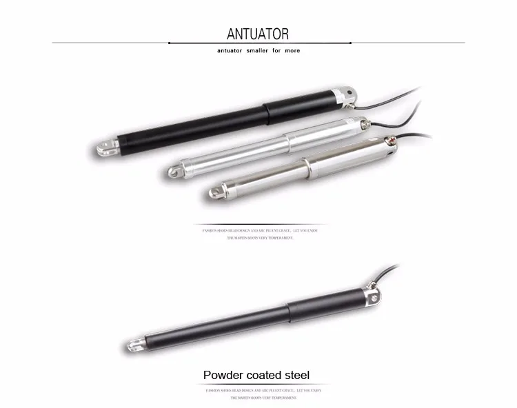
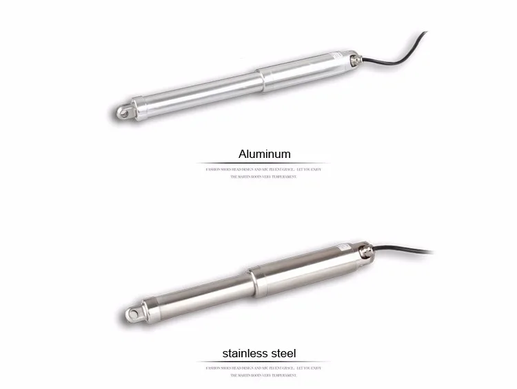
admin <![CDATA[tubular electric Linear Actuator 12/24V dc motor]]> http://rttheme19.rtthemes.com/2015/02/18/standart-post-2-2/ 2017-05-26T06:05:25Z 2015-01-18T23:03:20Z 12/24V dc motor ,tubular mini electric Linear Actuator Parameter: Load:100-6000N Speed:3.5-55mm/s Stroke:0-400mm IP67,IP67M Hall Sensor,Over current protection,Limit switch tubular mini electric Linear Actuator Main features: . Normal Tempeture range:-5°C to 40°C . Duty cycle: Max. 10% or 2 minutes in use followed by 18 min.Rest . Very small dimensions and elegant design . High efficiency DC permanent magnet industrial motor 12V/24V with planetary gear . IP54 &  IP66 protection class , Waterproof and dust-proof . Over current circuit protection . Hall sensors for precision control and positioning . No load noise: 50dB .Certified:CE . Diameter 52mm actuator’s material is aluminum Technical parameters    Max.Load(N)       […]

The post tubular electric Linear Actuator 12/24V dc motor appeared first on MOTOR.

]]>

12/24V dc motor ,tubular mini electric Linear Actuator

Parameter:

Load:100-6000N

Speed:3.5-55mm/s

Stroke:0-400mm

IP67,IP67M

Hall Sensor,Over current protection,Limit switch

tubular mini electric Linear Actuator Main features:

. Normal Tempeture range:-5°C to 40°C

. Duty cycle: Max. 10% or 2 minutes in use followed by 18 min.Rest

. Very small dimensions and elegant design

. High efficiency DC permanent magnet industrial motor 12V/24V with planetary gear

. IP54 &  IP66 protection class , Waterproof and dust-proof

. Over current circuit protection

. Hall sensors for precision control and positioning

. No load noise: 50dB

.Certified:CE

. Diameter 52mm actuator’s material is aluminum

12/24V dc motor ,tubular mini electric Linear Actuator12/24V dc motor ,tubular mini electric Linear Actuator

Technical parameters

   Max.Load(N)       100       300      400       800      1200     1800     2300
  Speed(mm/s)        30        17       14        7         5       3     2.3


  Stroke(mm)      50     100     150   200     250     300     350     400      Customize


Q1: When can I get the quotation?

A1: Usually you need to send below information, we will quote within 12 hours after we get it.

1) For customization: material, size, input,  Load  capacity,quantity, color speed  or frequency  , etc.

Q2: Can you help with the design?

A2: Yes, we have a professional team having rich experience in linear actuator  design and manufacturing.

Just tell us your ideas and we will help to carry our your ideas into perfect linear actuator

Q3: How long can I expect to get the sample?

A4: After you pay the sample freight charge and send us confirmed files, the samples will be ready in 3-7 days.

The samples will be sent to you via express and arrived in 3-5 workdays.

Q4: What about the lead time for mass production?

Honestly, it depends on the order quantity and the season you place the order. Generally speaking,

we suggest that you start to inquire two months before the date you would like to get the products at your country.

The post tubular electric Linear Actuator 12/24V dc motor appeared first on MOTOR.

]]>
0
admin <![CDATA[Brushed DC electric motor]]> http://rttheme19.rtthemes.com/2015/02/19/gallery-post-type-2-2/ 2017-05-26T09:18:00Z 2015-01-16T23:03:20Z Brushed DC electric motor A stepper motor or step motor or stepping motor is a brushless DC electric motor that divides a full rotation into a number of equal steps. The motor’s position can then be commanded to move and hold at one of these steps without any feedback sensor (an open-loop controller), as long […]

The post Brushed DC electric motor appeared first on MOTOR.

]]>
Brushed DC electric motor

A stepper motor or step motor or stepping motor is a brushless DC electric motor that divides a full rotation into a number of equal steps. The motor’s position can then be commanded to move and hold at one of these steps without any feedback sensor (an open-loop controller), as long as the motor is carefully sized to the application in respect to torque and speed.The brushed DC electric motor generates torque directly from DC power supplied to the motor by using internal commutation, stationary magnets (permanent or electromagnets), and rotating electrical magnets.

Advantages of a brushed DC motor include low initial cost, high reliability, and simple control of motor speed. Disadvantages are high maintenance and low life-span for high intensity uses. Maintenance involves regularly replacing the carbon brushes and springs which carry the electric current, as well as cleaning or replacing the commutator. These components are necessary for transferring electrical power from outside the motor to the spinning wire windings of the rotor inside the motor. Brushes consist of conductors.

Brushless
Main articles: Brushless DC electric motor and Switched reluctance motor

Typical brushless DC motors use one or more permanent magnets in the rotor and electromagnets on the motor housing for the stator. A motor controller converts DC to AC. This design is mechanically simpler than that of brushed motors because it eliminates the complication of transferring power from outside the motor to the spinning rotor. The motor controller can sense the rotor’s position via Hall effect sensors or similar devices and can precisely control the timing, phase, etc., of the current in the rotor coils to optimize torque, conserve power, regulate speed, and even apply some braking. Advantages of brushless motors include long life span, little or no maintenance, and high efficiency. Disadvantages include high initial cost, and more complicated motor speed controllers. Some such brushless motors are sometimes referred to as “synchronous motors” although they have no external power supply to be synchronized with, as would be the case with normal AC synchronous motors.
Uncommutated

Other types of DC motors require no commutation.

Homopolar motor – A homopolar motor has a magnetic field along the axis of rotation and an electric current that at some point is not parallel to the magnetic field. The name homopolar refers to the absence of polarity change. Homopolar motors necessarily have a single-turn coil, which limits them to very low voltages. This has restricted the practical application of this type of motor.
Ball bearing motor – A ball bearing motor is an unusual electric motor that consists of two ball bearing-type bearings, with the inner races mounted on a common conductive shaft, and the outer races connected to a high current, low voltage power supply. An alternative construction fits the outer races inside a metal tube, while the inner races are mounted on a shaft with a non-conductive section (e.g. two sleeves on an insulating rod). This method has the advantage that the tube will act as a flywheel. The direction of rotation is determined by the initial spin which is usually required to get it going.

Permanent magnet stators
Main article: Permanent-magnet electric motor

A PM motor does not have a field winding on the stator frame, instead relying on PMs to provide the magnetic field against which the rotor field interacts to produce torque. Compensating windings in series with the armature may be used on large motors to improve commutation under load. Because this field is fixed, it cannot be adjusted for speed control. PM fields (stators) are convenient in miniature motors to eliminate the power consumption of the field winding. Most larger DC motors are of the “dynamo” type, which have stator windings. Historically, PMs could not be made to retain high flux if they were disassembled; field windings were more practical to obtain the needed amount of flux. However, large PMs are costly, as well as dangerous and difficult to assemble; this favors wound fields for large machines.

To minimize overall weight and size, miniature PM motors may use high energy magnets made with neodymium or other strategic elements; most such are neodymium-iron-boron alloy. With their higher flux density, electric machines with high-energy PMs are at least competitive with all optimally designed singly fed synchronous and induction electric machines. Miniature motors resemble the structure in the illustration, except that they have at least three rotor poles (to ensure starting, regardless of rotor position) and their outer housing is a steel tube that magnetically links the exteriors of the curved field magnets.
Wound stators
A field coil may be connected in shunt, in series, or in compound with the armature of a DC machine (motor or generator)
Main article: universal motor
See also: Excitation (magnetic)

There are three types of electrical connections between the stator and rotor possible for DC electric motors: series, shunt/parallel and compound (various blends of series and shunt/parallel) and each has unique speed/torque characteristics appropriate for different loading torque profiles/signatures.
Types

There are three main types of stepper motors:

  • Permanent magnet stepper
  • Hybrid synchronous stepper
  • Variable reluctance stepper


The post Brushed DC electric motor appeared first on MOTOR.

]]>
0