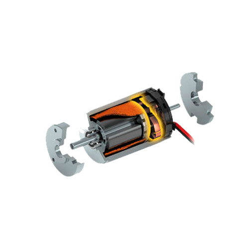
brushed DC motor
is an internally commutated electric motor designed to be run from a direct current power source. Brushed motors were the first commercially important application of electric power to driving mechanical energy, and DC distribution systems were used for more than 100 years to operate motors in commercial and industrial buildings. Brushed DC motors can be varied in speed by changing the operating voltage or the strength of the magnetic field. Depending on the connections of the field to the power supply, the speed and torque characteristics of a brushed motor can be altered to provide steady speed or speed inversely proportional to the mechanical load. Brushed motors continue to be used for electrical propulsion, cranes, paper machines and steel rolling mills. Since the brushes wear down and require replacement, brushless DC motors using power electronic devices have displaced brushed motors from many applications. The following graphics illustrate a simple, two-pole, brushed, DC motor.When a current passes through the coil wound around a soft iron core, the side of the positive pole is acted upon by an upwards force, while the other side is acted upon by a downward force. According to Fleming’s left hand rule, the forces cause a turning effect on the coil, making it rotate. To make the motor rotate in a constant direction, “direct current” commutators make the current reverse in direction every half a cycle (in a two-pole motor) thus causing the motor to continue to rotate in the same direction.
A problem with the motor shown above is that when the plane of the coil is parallel to the magnetic field—i.e. when the rotor poles are 90 degrees from the stator poles—the torque is zero. In the pictures above, this occurs when the core of the coil is horizontal—the position it is just about to reach in the last picture on the right. The motor would not be able to start in this position. However, once it was started, it would continue to rotate through this position by momentum.
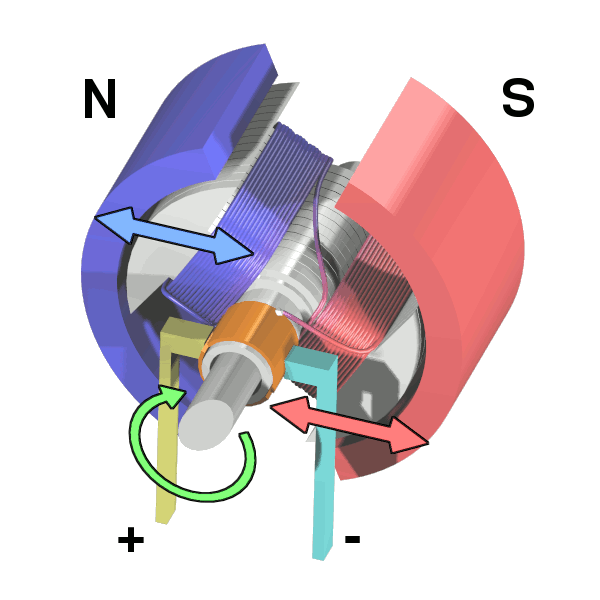
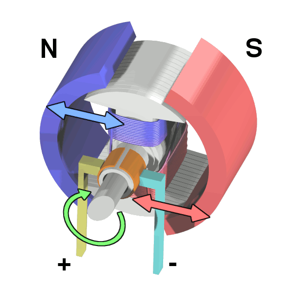
There is a second problem with this simple pole design. At the zero-torque position, both commutator brushes are touching (bridging) both commutator plates, resulting in a short-circuit. The power leads are shorted together through the commutator plates, and the coil is also short-circuited through both brushes (the coil is shorted twice, once through each brush independently). Note that this problem is independent of the non-starting problem above; even if there were a high current in the coil at this position, there would still be zero torque. The problem here is that this short uselessly consumes power without producing any motion (nor even any coil current.) In a low-current battery-powered demonstration this short-circuiting is generally not considered harmful. However, if a two-pole motor were designed to do actual work with several hundred watts of power output, this shorting could result in severe commutator overheating, brush damage, and potential welding of the brushes—if they were metallic—to the commutator. Carbon brushes, which are often used, would not weld. In any case, a short like this is very wasteful, drains batteries rapidly and, at a minimum, requires power supply components to be designed to much higher standards than would be needed just to run the motor without the shorting.
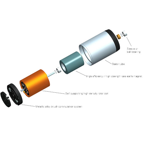
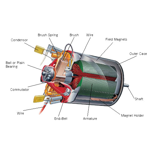
The inside of a miniature DC motor as would be found in a toy.
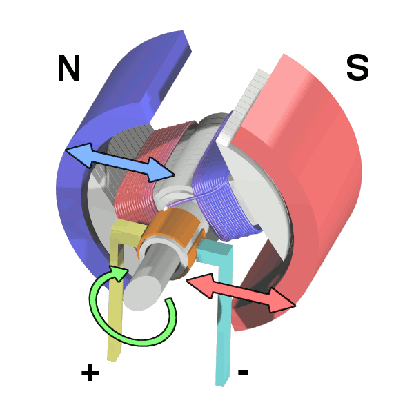
One simple solution is to put a gap between the commutator plates which is wider than the ends of the brushes. This increases the zero-torque range of angular positions but eliminates the shorting problem; if the motor is started spinning by an outside force it will continue spinning. With this modification, it can also be effectively turned off simply by stalling (stopping) it in a position in the zero-torque (i.e. commutator non-contacting) angle range. This design is sometimes seen in homebuilt hobby motors, e.g. for science fairs and such designs can be found in some published science project books. A clear downside of this simple solution is that the motor now coasts through a substantial arc of rotation twice per revolution and the torque is pulsed. This may work for electric fans or to keep a flywheel spinning but there are many applications, even where starting and stopping are not necessary, for which it is completely inadequate, such as driving the capstan of a tape transport, or any instance where to speed up and slow down often and quickly is a requirement. Another disadvantage is that, since the coils have a measure of self inductance, current flowing in them cannot suddenly stop. The current attempts to jump the opening gap between the commutator segment and the brush, causing arcing.
Even for fans and flywheels, the clear weaknesses remaining in this design—especially that it is not self-starting from all positions—make it impractical for working use, especially considering the better alternatives that exist. Unlike the demonstration motor above, DC motors are commonly designed with more than two poles, are able to start from any position, and do not have any position where current can flow without producing electromotive power by passing through some coil.
brushed DC motor
Many common small brushed DC motors used in toys and small consumer appliances, the simplest mass-produced DC motors to be found, have three-pole armatures. The brushes can now bridge two adjacent commutator segments without causing a short circuit. These three-pole armatures also have the advantage that current from the brushes either flows through two coils in series or through just one coil. Starting with the current in an individual coil at half its nominal value (as a result of flowing through two coils in series), it rises to its nominal value and then falls to half this value. The sequence then continues with current in the reverse direction.